Jual hosting unlimited disk space

jual web hosting unlimited dengan harga super murah, hanya Rp80.000 PER TAHUN lho www.hostation.org

This is default featured slide 2 title

Go to Blogger edit html and find these sentences.Now replace these sentences with your own descriptions.

This is default featured slide 3 title

Go to Blogger edit html and find these sentences.Now replace these sentences with your own descriptions.

This is default featured slide 4 title

Go to Blogger edit html and find these sentences.Now replace these sentences with your own descriptions.

This is default featured slide 5 title

Go to Blogger edit html and find these sentences.Now replace these sentences with your own descriptions.

simple and easy emergency light and alarm circuit

This is a simple and easy emergency light and alarm circuit. This circuit is permanently plugged into a mains socket and NI-CD batteries are trickle-charged. When a power outage occurs, the lamp automatically illuminates. Instead of illuminating a lamp, an alarm sounder can be chosen.

When power supply is restored, the lamp or the alarm is switched-off. A switch provides a "latch-up" function, in order to extend lamp or alarm operation even when power is restored.

Emergency Light and Alarm circuit diagram

Component parts list:

R1 = 220K
R2 = 470R
R3 = 390R
R4 = 1K5
R5 = 1R
R6 = 10K
R7 = 330K
R8 = 470R
R9 = 100R
C1 = 330nF/400V Polyester Capacitor
C2 = 10µF/63V Electrolytic Capacitor
C3 = 100nF/63V Polyester Capacitor
C4 = 10nF/63V Polyester Capacitor
D1-D5 = 1N4007
D6 = LED Green
D7 = 1N4148
Q1,Q3,Q4 = BC547
Q2,Q5 = BC327
SW1,SW2 = SPST Switches
SW3 = SPDT Switch
LP1 = 2.2V or 2.5V 250-300mA Torch Lamp Bulb
SPKR = 8 Ohm Loudspeaker
B1 = 2.5V Battery (two AA NI-CD rechargeable cells wired in series)
PL1 = Male Mains plug

Circuit Works:
Mains voltage is reduced to about 12V DC at C2's terminals, by means of the reactance of C1 and the diode bridge (D1-D4). This avoids the use of a mains transformer.

Trickle-charging current for the battery B1 is provided by the series resistor R3, D5 and the green LED D6 that also monitors the presence of mains supply and correct battery charging.
Q2 & Q3 form a self-latching pair that start operating when a power outage occurs. In this case, Q1 biasing becomes positive, so this transistor turns on the self latching pair.

If SW3 is set as shown in the circuit diagram, the lamp illuminates via SW2, which is normally closed; if set the other way, a square wave audio frequency generator formed by Q4, Q5 and related components is activated, driving the loudspeaker.

If SW1 is left open, when mains supply is restored the lamp or the alarm continue to operate. They can be disabled by opening the main on-off switch SW2.

If SW1 is closed, restoration of the mains power supply terminates lamp or alarm operation, by applying a positive bias to the Base of Q2.

Notes:
  • Close SW2 after the circuit is plugged.
  • Warning! The circuit is connected to 230Vac mains, then some parts in the circuit board are subjected to lethal potential!. Avoid touching the circuit when plugged and enclose it in a plastic box.


Emergency Light and Alarm circuit source: http://www.redcircuits.com/Page45.htm

a touch activated alarm system

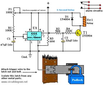
This is a touch activated alarm system. Your alarm system will be activated when someone touching the "trigger". You may use this circuit at your home door, your vehicle etc.
Touch Activated Alarm circuit diagram

Parts list:


R1 = 100K
R2 = 56K
R3 = 10M
R4 = 220K
P1 = 100K
D1 = 1N4004
T1 = 2N3904, or equivalent
U1 = 555 Timer*
C1 = 47μF/16V**
C2 = 33μF/16V**
Re1 = Relay***

Notes:

*The 555 can be a LM, NE, or MC(cmos) type, they're all pin-compatible.

**C1/C2's working voltage ought to be elevated to 25V in the event you decide to go with a 12V power source. Rule of thumb: the operating voltage of capacitors are at least double the supplied voltage, in other words, if the power source is 9 Volt, your capacitor(s) is a minimum of 18V. Transistor T1 could be any approximate substitute.

*** Use any appropriate relay for the project and if you're not tight on area, use any size. I've build this specific circuit to prevent students from fiddling using the security cameras in pc labs at the University I'm employed. I made sure the metal casing was not grounded. But as being the schematic shows you are able to essentially hook it as much as any type of metal surface. I utilized a 12-vdc power supply. Use any suitable relay to deal with your specifications. A 'RESET' switch (Normally Closed) can be added between the constructive and also the 'arrow-with-the-+'. The trigger (touch) wire is connected to pin 2 of the 555 and will trigger the relay, using the body resistance, when touched. It is apparent that the 'touching' component has to be clean and can make good contact using the trigger wire. This particular circuit might not be suitable for all applications. Just in case you wonder why pin 5 is not listed within the schematic diagram; it is not really required. In particular noisy circumstances a little ceramic capacitor is placed between pin 5 and ground. It will no harm to put one or leave it out.

Additional note: For those of you who didn't discover, there's an approximate 5-second delay build-in before activation of the relay to avoid false triggering, or perhaps a 'would-be' thief, and so on.

Circuit design by Tony van Roon.

Electronic Chirping Canary Circuits

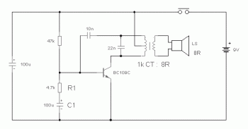
Electronic Chirping Canary Circuit diagram

Well, for those of you who want to make a small project, this alarm may be an option for you. This circuit will generate the canary chirping sound. The chirp sound of a canary is generated by the oscillation process by resistor R1 and capacitor C1. The capacitor, having a capacitance value of 100 uF, is charging through the resistor, having a resistance of 4.7 K ohms. During this stage, R1 is the bias for the transistor making it operate in the cut off. When the transistor is in cut off mode, the base-emitter voltage is very minimal for any considerable current to flow. This mode triggers the oscillation to end but will start again once the capacitor discharges across the transmitter’s base-emitter circuit.

The frequency of the chirp may be modified by changing the values of the resistor and capacitor. The charging of the capacitor occurs when operating the push button switch. By releasing the button, the chirping runs quicker whilst the oscillation weakens.

The loudspeaker is being driven and coupled to the circuit by the miniature audio transformer of LT700 which having a frequency of 1 kHz. This circuit can be supplied with 9V battery.

Electronic chirping canary circuit source: http://www.elecpod.com/circuit/av/2010/03011410.html

bassic how to make motor cicle alarm

This is a very basic motorcycle alarm design circuit which can be used to secure your motorcycle with very low in cost.

Design schematic:
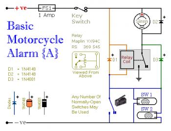
Basic Motorcycle Alarm circuit diagram

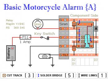
Circuit Number Five uses a SPCO/SPDT relay - but you actually only require to make use of a SPST relay. In case you are going to make use of the veroboard layout supplied - you will require to make use of the style of relay specified. But you are able to develop the alarm making use of whatever style of relay you've accessible.

Circuit Notes:
Any number of normally-open switches might be employed. Fit the mercury switches to ensure that they close when the steering is moved or when the bike is lifted off its side-stand or pushed forward off its centre-stand. Use micro-switches to secure removable panels and also the lids of panniers and so on. When 1 of the trigger-switches is closed - the relay will energize as well as the siren will sound.

You are able to select what will happen up coming. Should you develop the circuit as shown, the siren will continue to sound until you turn it off - or until the battery is exhausted. But, in the event you leave out D3 - the siren will stop sounding right away the trigger-switch is re-opened.

Whilst you are inside earshot of your machine - the former configuration is greatest. You are able to usually turn off the alarm your self. But in case you are going to be away from your bike for any length of time - and you do not wish to trigger a nuisance - then the latter configuration is possibly much more suitable. In the event you consist of a SPST switch in series with D3 - you'll be able to pick the behaviour that finest suits the circumstances at any given time.

Components placement:
Basic Motorcycle Alarm pcb design


Relay coils and some sounders generate high reverse-voltage spikes which will destroy sensitive electronic components. D1 and D2 are there to short-circuit these spikes just before they are able to do any harm. Even though there's absolutely nothing within the alarm circuit itself that might be damaged - I've no concept what other electronic equipment may be connected to the exact same power supply. So I included the two diodes as a precaution. If you are satisfied that there is absolutely nothing on your bike that may be damaged in this way - you'll be able to leave out the two diodes.

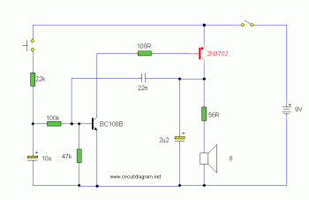
Electronic Siren Circuit schema

Electronic Siren circuit diagram


This is the schematic diagram of electronic siren circuit. The sound produced imitates the rise and fall of an American police siren. When very first switched on, the 10uF capacitors is discharged and each transistors are off. When the push button switch is pressed to 10uF capacitor will charge via the 22k resistor. This voltage is applied towards the base of the BC108B which will turn on slowly. When the switch is released the capacitor will discharge via the 100k and 47k base resistors and also the transistor will slowly turn off. The change in voltage alters the frequency of the electronic siren.


Electric current drain is fairly high in this electronic siren circuit so a appropriate power supply is needed. The duration the tone takes to rise and fall is determined by the 10uF and 22k resistor. These values may possibly be varied for various effects.

the other one multiple backlink free service

 Back link it's a big trouble for every seo warrior several month ago i try to use back link exchange with the other blog /site and i found like this
"A free automatic backlinks generator service, free auto backlinks this website offer free auto backlinks service for blogger or web owner who want to get instant backlink for their blog or websites. We know how important is SEO to increase traffic, pagerank, and alexa rank.

Just copy this banner code to your website or blog »"

I add the image link just like the instruction from the site, i try to click the link than my link was displayed on the site, but less than 1 hour my link was disappear, in a month i check my alexa link check, this service are detect any sites who linked to us and i didn't find any link from the sites, 
it's means the back link service like this is use less, than today i'd like to make an article about a site who give a free multiple backlink.

a free multiple back link service, like we know that back link are very important for seo warrior, and here is a new free multiple backlink service

http://coplaz.com/backlink
http://multybacklink.co.cc

multiple search engine submition for free also
http://multybacklink.co.cc/searchenginesubmit/
 
this is a new service of this blog, but looks power full for me. have a nice try

the most beautyfull money design

have you ever seen The most beautyfull money design in the world here it's some of beautyfull money


Faroe Island Kronurs

Hongkong Dollar


Cook Islands Dollar


New Zealand Dollar


Iceland Kronurs


Sao Tome & Principe Dobras


The Maldives Rufiyaa


The French Pacific Territories Franc


Comoro Franc


beautyfull money right?