Magic Lights Circuit using Bi-Colour LED

This is the magic lights circuit which use bi-colour LED as the output to provide the light. The circuit uses 14 bi-colour (red and green) LEDs having 3 terminals each. Various dancing colour patterns are generated utilizing this circuit considering that each LED can create three various colours. The middle terminal (pin 2) of the LEDs will be the common cathode pin that is grounded. When a positive voltage is applied to pin one, it emits red light. Similarly, when positive voltage is applied to pin 3. it emits green light. And when positive voltage is simultaneously applied to its pins 1 and 3, it emits amber light.
The circuit could be implemented for decorative lights. The IC1 (timer IC 555) is applied in astable mode of multivibrator to produce clock signal for IC2 and IC3 (CD4518) that are dual BCD counters.
The two counters of each one of these ICs have already been cascaded to acquire 8 outputs from each. The outputs from IC2 and IC3 are connected to IC4 through IC7 that are BCD to 7-segment latch/decoder/driver ICs. Therefore we acquire a complete of 14 segment outputs from each of the IC pairs composed of IC4 plus IC5 and IC6 plus IC7. While outputs from former pair are connected to pin No. 1 of all the 14 bi-colour LEDs through current limiting resistors, the ouputs of the latter pair are similarly connected to pin No.3 of all the bi-colour LEDs to acquire a magical dancing lights effect.
Cricket Chirping Sound Generator
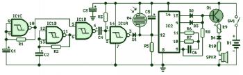
This is the circuit diagram of cricket chirping sound generator based on IC 4060, a 14 stage ripple counter and oscillator IC. A suitable audio wave form is produced by IC2 and related electronic components, driving the mini speaker through Q1. To allow a more real-life behavior, the chirp is interrupted in a pseudo-casual way by two timers built around IC1C and IC1D, whose outputs are mixed into IC1B and further time-delayed by IC1A, driving the reset pin of IC2.
 This is the circuit diagram of mice repellent. Mice are animals that are very annoying, because sometimes he is damaging the object stored in the form of archives that are still valuable.
Electronic Chirping Canary Circuit
Well, for those of you who want to make a small project, this alarm may be an option for you. This circuit will generate the canary chirping sound. The chirp sound of a canary is generated by the oscillation process by resistor R1 and capacitor C1. The capacitor, having a capacitance value of 100 uF, is charging through the resistor, having a resistance of 4.7 K ohms. During this stage, R1 is the bias for the transistor making it operate in the cut off. When the transistor is in cut off mode, the base-emitter voltage is very minimal for any considerable current to flow. This mode triggers the oscillation to end but will start again once the capacitor discharges across the transmitter’s base-emitter circuit.
The frequency of the chirp may be modified by changing the values of the resistor and capacitor. The charging of the capacitor occurs when operating the push button switch. By releasing the button, the chirping runs quicker whilst the oscillation weakens.
The loudspeaker is being driven and coupled to the circuit by the miniature audio transformer of LT700 which having a frequency of 1 kHz. This circuit can be supplied with 9V battery.
Electronic chirping canary circuit source: http://www.elecpod.com/circuit/av/2010/03011410.html
Really Simple LED Flasher with LM3909
Light Detector
High Quality Intercom circuit
Running LED
Zone Alarm System
This is the circuit of alarm system with 5 independent zones. Suitable for a small office or home environment. It uses just 3 CMOS IC's and features a timed entry / exit zone, 4 immediate zones and a panic button. There are indicators for each zone a "system armed" indicator.
Zone 1 is a timed zone which must be used as the entry and exit point of the building. Zones 2 - 5 are immediate zones, which will trigger the alarm with no delay. Some RF immunity is provided for long wiring runs by the input capacitors, C1-C5. C7 and R14 also form a transient suppresser. The key switch acts as the Set/Unset and Reset switch. For good security this should be the metal type with a key.
Circuit works:
At switch on, C6 will charge via R11, this acts as the exit delay and is set to around 30 seconds. This can be altered by varying either C6 or R11. Once the timing period has elapsed, LED6 will light, meaning the system is armed. LED6 may be mounted externally (at the bell box for example) and provides visual indication that the system has set. Once set any contact that opens will trigger the alarm, including Zone 1. To prevent triggering the alarm on entry to the building, the concealed re-entry switch must be operated. This will discharge C6 and start the entry timer. The re-entry switch could be a concealed reed switch, located anywhere in a door frame, but invisible to the eye. The panic switch, when pressed, will trigger the alarm when set. Relay contacts RLA1 provide the latch, RLA2 operate the siren or buzzer.
Simple Electronic Buzzer
This is a simple electronic buzzer circuit diagram. Cheap and easy to build.
The 555 is used as astable multivibrator operating at about 1kHz and produces a shrill noise when switched on. The frequency can be adjusted by varying the 10K resistor. You may change the 10K resistor with variable resistor.
Digital Clock
Dancing LEDs
This is dancing LEDs schematic diagram. the LEDs will dance squence to audio (music or speaking) from the microphone.
Components list:
R1_____________10K 1/4W Resistor
R2,R3__________47K 1/4W Resistors
R4______________1K 1/4W Resistor
R5,R6,R7______100K 1/4W Resistors
R8____________820R 1/4W Resistor
C1,C3_________100nF 63V Ceramic or Polyester Capacitors
C2_____________10?F 50V Electrolytic Capacitor
C4____________330nF 63V Polyester Capacitor (See Notes)
C5____________100?F 25V Electrolytic Capacitor
D1___________1N4148 75V 150mA Diode
D2-D11_________5 or 3mm. LEDs (any type and color)
IC1___________LM358 Low Power Dual Op-amp
IC2____________4017 Decade counter with 10 decoded outputs IC
M1_____________Miniature electret microphone
SW1____________SPST miniature Slider Switch
B1_______________9V PP3 Battery
Clip for PP3 Battery
Additional circuit parts (see Notes):
R9,R10_________10K 1/4W Resistors
R11____________56R 1/4W Resistor
D12,D13 etc.____5 or 3mm. LEDs (any type and color)
Q1,Q2_________BC327 45V 800mA PNP Transistors
Q3____________BC337 45V 800mA NPN Transistor
Sound Effects Alarm Generator
This schematic in very simple and easy to made. The IC produces all the sound effects, the output at Pin 3 being amplified by the transistor. A 64 ohm loudspeaker can be substituted in place of the 56 ohm resistor and 8 ohm loudspeaker. The 2 pole 4 way switch controls the sound effects. Position 1 (as drawn) being a Police siren, position 2 is a fire engine sound, 3 is an ambulance and position 4 is a machine gun effect. The IC is manufactured by UMC and was available from Maplin electronics code UJ45Y. At the time of writing this has now been discontinued, but they have have limited stocks available.
Multi tone alarm

This is a simple and easy to build multi tone alarm circuit that can be used in burglar alarms or sirens. The circuit is based on dual op-amp MC1458 and LM 380. The two op amps inside the MC 1458 are used to produce square and triangular waves.LM 380 is used to amplify the output.The first op amp IC1a is wired as an astable multi vibrator and second op amp IC1b is wired as an integrator, to make the square wave triangle.
The two output square ans sine can be selected using switch S1 to the input of IC2 which amplifies it to drive the speaker. POT R4 can be used for tone adjustment.
Notes .
Basic Analog Flip Flop Schematics
Dancing Lights
 This circuit is very simple... you can use this circuit for decoration purposes or as an indicator. Flashing or dancing speed of LEDs can be adjusted and various dancing patterns of lights can be formed.
The circuit consists of two astable multivibrators. One multivibrator is formed by transistors T1 and T2 while the other astable multivibrator is formed by T3 and T4. Duty cycle of each multivibrator can be varied by changing RC time constant. This can be done through potentiometers VR1 and VR2 to produce different dancing pattern of LEDs.
Flashy christmas light
This simple and inexpensive circuit built around a popular CMOS hex inverter IC CD4069UB offers four sequential switching outputs that may be used to control 200 LEDs (50 LEDs per channel), driven directly from mains supply. Input supply of 230V AC is rectified by the bridge rectifiers D1 to D4. After fullwave rectification, the average output voltage of about 6 volts is obtained across the filter comprising capacitor C1 and resistor R5.
Just a minute scoring board circuit
 You can use this circuit for quiz contests wherein any participant who presses his button (switch) before the other contestants, gets the first chance to answer a question. The circuit given here permits up to eight contestants with each one allotted a distinct number (1 to 8). The display will show the number of the contestant pressing his button before the others. Simultaneously, a buzzer will also sound.

This is the magic lights circuit which use bi-colour LED as the output to provide the light. The circuit uses 14 bi-colour (red and green) LEDs having 3 terminals each. Various dancing colour patterns are generated utilizing this circuit considering that each LED can create three various colours. The middle terminal (pin 2) of the LEDs will be the common cathode pin that is grounded. When a positive voltage is applied to pin one, it emits red light. Similarly, when positive voltage is applied to pin 3. it emits green light. And when positive voltage is simultaneously applied to its pins 1 and 3, it emits amber light.
The circuit could be implemented for decorative lights. The IC1 (timer IC 555) is applied in astable mode of multivibrator to produce clock signal for IC2 and IC3 (CD4518) that are dual BCD counters.
The two counters of each one of these ICs have already been cascaded to acquire 8 outputs from each. The outputs from IC2 and IC3 are connected to IC4 through IC7 that are BCD to 7-segment latch/decoder/driver ICs. Therefore we acquire a complete of 14 segment outputs from each of the IC pairs composed of IC4 plus IC5 and IC6 plus IC7. While outputs from former pair are connected to pin No. 1 of all the 14 bi-colour LEDs through current limiting resistors, the ouputs of the latter pair are similarly connected to pin No.3 of all the bi-colour LEDs to acquire a magical dancing lights effect.
Cricket Chirping Sound Generator

This is the circuit diagram of cricket chirping sound generator based on IC 4060, a 14 stage ripple counter and oscillator IC. A suitable audio wave form is produced by IC2 and related electronic components, driving the mini speaker through Q1. To allow a more real-life behavior, the chirp is interrupted in a pseudo-casual way by two timers built around IC1C and IC1D, whose outputs are mixed into IC1B and further time-delayed by IC1A, driving the reset pin of IC2.
Mice Repellent Circuit

To drive out the mice, you can create an electronic circuit of mice repellent as shown above. With 50KHz frequency generated by the timer IC 555. The mice would run because his ears will feel sore due to the signal frequency.
The work of this circuit is very simple. The timer IC act as the frequency generator, while the frequency value is decided by C1 and C3. The output of 555 will be amplified by the SC1162 transistor and then fed to the speaker so the audio signal can be heard by the mice.
Parts List:
R1 = 1K8
R2 = 1K
R3 = 5K6
R4 = 480R
C1 = 2,2nF
C2 = 0,022uF/6V
IC = 555
Q = SC1162
SP = Speaker 4 ohm
Electronic Siren Circuit
This is the schematic diagram of electronic siren circuit. The sound produced imitates the rise and fall of an American police siren. When very first switched on, the 10uF capacitors is discharged and each transistors are off. When the push button switch is pressed to 10uF capacitor will charge via the 22k resistor. This voltage is applied towards the base of the BC108B which will turn on slowly. When the switch is released the capacitor will discharge via the 100k and 47k base resistors and also the transistor will slowly turn off. The change in voltage alters the frequency of the electronic siren.
Electric current drain is fairly high in this electronic siren circuit so a appropriate power supply is needed. The duration the tone takes to rise and fall is determined by the 10uF and 22k resistor. These values may possibly be varied for various effects.
The work of this circuit is very simple. The timer IC act as the frequency generator, while the frequency value is decided by C1 and C3. The output of 555 will be amplified by the SC1162 transistor and then fed to the speaker so the audio signal can be heard by the mice.
Parts List:
R1 = 1K8
R2 = 1K
R3 = 5K6
R4 = 480R
C1 = 2,2nF
C2 = 0,022uF/6V
IC = 555
Q = SC1162
SP = Speaker 4 ohm
Electronic Siren Circuit

This is the schematic diagram of electronic siren circuit. The sound produced imitates the rise and fall of an American police siren. When very first switched on, the 10uF capacitors is discharged and each transistors are off. When the push button switch is pressed to 10uF capacitor will charge via the 22k resistor. This voltage is applied towards the base of the BC108B which will turn on slowly. When the switch is released the capacitor will discharge via the 100k and 47k base resistors and also the transistor will slowly turn off. The change in voltage alters the frequency of the electronic siren.
Electric current drain is fairly high in this electronic siren circuit so a appropriate power supply is needed. The duration the tone takes to rise and fall is determined by the 10uF and 22k resistor. These values may possibly be varied for various effects.
Electronic Chirping Canary Circuit

Well, for those of you who want to make a small project, this alarm may be an option for you. This circuit will generate the canary chirping sound. The chirp sound of a canary is generated by the oscillation process by resistor R1 and capacitor C1. The capacitor, having a capacitance value of 100 uF, is charging through the resistor, having a resistance of 4.7 K ohms. During this stage, R1 is the bias for the transistor making it operate in the cut off. When the transistor is in cut off mode, the base-emitter voltage is very minimal for any considerable current to flow. This mode triggers the oscillation to end but will start again once the capacitor discharges across the transmitter’s base-emitter circuit.
The frequency of the chirp may be modified by changing the values of the resistor and capacitor. The charging of the capacitor occurs when operating the push button switch. By releasing the button, the chirping runs quicker whilst the oscillation weakens.
The loudspeaker is being driven and coupled to the circuit by the miniature audio transformer of LT700 which having a frequency of 1 kHz. This circuit can be supplied with 9V battery.
Electronic chirping canary circuit source: http://www.elecpod.com/circuit/av/2010/03011410.html
Really Simple LED Flasher with LM3909
This is a very -very easy and simple LED flasher circuit with only needs three components that are: a flasher IC, a LED and a electrolytic capacitor.
 Component list:
Very nice for electronics newbie.. :)

LED1_________Red LED
C1___________100uf/16V
IC1__________LM3909
Very nice for electronics newbie.. :)
Light Detector
This is a circuit diagram of light detector. This circuit can be used as a sensor of automatic lamp switch, thic circuit also can be used for anti theft alarm circuit.
Schematic diagram:
Use variable resistor R1 to adjust the light threshold at which the circuit triggers. R1's value is chosen to match the photocells resistance at darkness. The circuit uses a CMOS 4001 IC. Gate U1a acts as the trigger, U1b and c form a latch. S1 to reset the circuit. You may used piezo buzzer or LED as output indicator, you may use both of them.
Schematic diagram:

Use variable resistor R1 to adjust the light threshold at which the circuit triggers. R1's value is chosen to match the photocells resistance at darkness. The circuit uses a CMOS 4001 IC. Gate U1a acts as the trigger, U1b and c form a latch. S1 to reset the circuit. You may used piezo buzzer or LED as output indicator, you may use both of them.
High Quality Intercom circuit
This is an intercom circuit which use LM380 as the audio amplifier and 2 transistors as the microphone pre amplifier. The sound quality will be good enough with low cost building.

This circuit consists of two identical intercom units. Each unit contains a power supply, microphone preamplifier, audio amplifier and a Push To Talk (PTT) relay circuit. Only 2 wires are required to connect the units together. Due to the low output impedance of the mic preamp, screened cable is not necessary and ordinary 2 core speaker cable, or bell wire may be used.
Detail explanation about this intercom circuit include the PCB layout, please visit this page
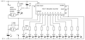
Running LED
This is the running LED circuit diagram. The LED will "running" (on) one by one. You can use this circuit for many purpose like motorcycle lamp, running character and much more.
Here the schematic diagram with IC timer 555:

And use this circuit use NAND logic:
Here the schematic diagram with IC timer 555:

And use this circuit use NAND logic:

Zone Alarm System

This is the circuit of alarm system with 5 independent zones. Suitable for a small office or home environment. It uses just 3 CMOS IC's and features a timed entry / exit zone, 4 immediate zones and a panic button. There are indicators for each zone a "system armed" indicator.
Zone 1 is a timed zone which must be used as the entry and exit point of the building. Zones 2 - 5 are immediate zones, which will trigger the alarm with no delay. Some RF immunity is provided for long wiring runs by the input capacitors, C1-C5. C7 and R14 also form a transient suppresser. The key switch acts as the Set/Unset and Reset switch. For good security this should be the metal type with a key.
Circuit works:
At switch on, C6 will charge via R11, this acts as the exit delay and is set to around 30 seconds. This can be altered by varying either C6 or R11. Once the timing period has elapsed, LED6 will light, meaning the system is armed. LED6 may be mounted externally (at the bell box for example) and provides visual indication that the system has set. Once set any contact that opens will trigger the alarm, including Zone 1. To prevent triggering the alarm on entry to the building, the concealed re-entry switch must be operated. This will discharge C6 and start the entry timer. The re-entry switch could be a concealed reed switch, located anywhere in a door frame, but invisible to the eye. The panic switch, when pressed, will trigger the alarm when set. Relay contacts RLA1 provide the latch, RLA2 operate the siren or buzzer.
Simple Electronic Buzzer

This is a simple electronic buzzer circuit diagram. Cheap and easy to build.
The 555 is used as astable multivibrator operating at about 1kHz and produces a shrill noise when switched on. The frequency can be adjusted by varying the 10K resistor. You may change the 10K resistor with variable resistor.
Digital Clock
This is digital clock schematic diagram. You can find the complete explanatio include the component part list on the original page.


Dancing LEDs

This is dancing LEDs schematic diagram. the LEDs will dance squence to audio (music or speaking) from the microphone.
Components list:
R1_____________10K 1/4W Resistor
R2,R3__________47K 1/4W Resistors
R4______________1K 1/4W Resistor
R5,R6,R7______100K 1/4W Resistors
R8____________820R 1/4W Resistor
C1,C3_________100nF 63V Ceramic or Polyester Capacitors
C2_____________10?F 50V Electrolytic Capacitor
C4____________330nF 63V Polyester Capacitor (See Notes)
C5____________100?F 25V Electrolytic Capacitor
D1___________1N4148 75V 150mA Diode
D2-D11_________5 or 3mm. LEDs (any type and color)
IC1___________LM358 Low Power Dual Op-amp
IC2____________4017 Decade counter with 10 decoded outputs IC
M1_____________Miniature electret microphone
SW1____________SPST miniature Slider Switch
B1_______________9V PP3 Battery
Clip for PP3 Battery
Additional circuit parts (see Notes):
R9,R10_________10K 1/4W Resistors
R11____________56R 1/4W Resistor
D12,D13 etc.____5 or 3mm. LEDs (any type and color)
Q1,Q2_________BC327 45V 800mA PNP Transistors
Q3____________BC337 45V 800mA NPN Transistor
Circuit operation:
IC1A amplifies about 100 times the audio signal picked-up by the microphone and drives IC1B acting as peak-voltage detector. Its output peaks are synchronous with the peaks of the input signal and clock IC2, a ring decade counter capable of driving up to ten LEDs in sequence.
An additional circuit allows the driving of up to ten strips, made up by five LEDs each (max.), at 9V supply. It is formed by a 10mA constant current source (Q1 & Q2) common to all LED strips and by a switching transistor (Q3), driving a strip obtained from 2 to 5 series-connected LEDs. Therefore one transistor and its Base resistor are required to drive each strip used.
An additional circuit allows the driving of up to ten strips, made up by five LEDs each (max.), at 9V supply. It is formed by a 10mA constant current source (Q1 & Q2) common to all LED strips and by a switching transistor (Q3), driving a strip obtained from 2 to 5 series-connected LEDs. Therefore one transistor and its Base resistor are required to drive each strip used.
Notes:
- The sensitivity of the circuit can be varied changing R4 value.
- C4 value can be varied from 220 to 470nF in order to change the circuit speed-response to music peaks.
- Adopting the additional circuit, only one item for R10, R11, Q1 and Q2 is required to drive up to ten LED strips. On the contrary, one item of R9 and Q3 is necessary to drive each strip you decided to use.
- Each R9 input must be connected to IC2 output pins, in place of the LEDs D2-D11 shown. R8 must also be omitted.
- Whishing to use a lower number of LEDs or LED strips, pin #15 of IC2 must be disconnected from ground and connected to the first unused output pin. Example:
if you decided to use 5 LEDs, pin #15 of IC2 must be connected to pin #1; if you decided to use 8 LEDs, pin #15 of IC2 must be connected to pin #9 etc. - Current drawing of the circuit is about 10mA.
- Whishing to use a wall-plug transformer-supply instead of a 9V battery, you can supply the circuit at 12V, allowing the use of up to 6 LEDs per strip, or at 15V, allowing the use of up to 7 LEDs per strip.
Sound Effects Alarm Generator

This schematic in very simple and easy to made. The IC produces all the sound effects, the output at Pin 3 being amplified by the transistor. A 64 ohm loudspeaker can be substituted in place of the 56 ohm resistor and 8 ohm loudspeaker. The 2 pole 4 way switch controls the sound effects. Position 1 (as drawn) being a Police siren, position 2 is a fire engine sound, 3 is an ambulance and position 4 is a machine gun effect. The IC is manufactured by UMC and was available from Maplin electronics code UJ45Y. At the time of writing this has now been discontinued, but they have have limited stocks available.
Multi tone alarm

This is a simple and easy to build multi tone alarm circuit that can be used in burglar alarms or sirens. The circuit is based on dual op-amp MC1458 and LM 380. The two op amps inside the MC 1458 are used to produce square and triangular waves.LM 380 is used to amplify the output.The first op amp IC1a is wired as an astable multi vibrator and second op amp IC1b is wired as an integrator, to make the square wave triangle.
The two output square ans sine can be selected using switch S1 to the input of IC2 which amplifies it to drive the speaker. POT R4 can be used for tone adjustment.
Notes .
- IC1a and IC1b are same. So their power supply is common.Wire exactly as shown in figure, nothing to care.
- C1 and C2 are ceramic, C3 is electrolytic capacitor.
- Pin 6 of IC2 (inv input) has no connection.
- A dual power supply is needed here.
Basic Analog Flip Flop Schematics
This schematics is a basic analog flip flop. As we know, there are analog flip flop which built using analog components like ordinary transistor and digital flip flop build using digital logic IC (integrated circuit) like TTL IC.
and here the result:

To control the speed of light's "on" and "off" in another word "control the flash rate", you can replace the Resistor 10K with variable resistor 20K or replace the electrolytic capacitor 100uF with other value.
Flip flop PCB layout:


and here the result:
To control the speed of light's "on" and "off" in another word "control the flash rate", you can replace the Resistor 10K with variable resistor 20K or replace the electrolytic capacitor 100uF with other value.
Flip flop PCB layout:
Dancing Lights

The circuit consists of two astable multivibrators. One multivibrator is formed by transistors T1 and T2 while the other astable multivibrator is formed by T3 and T4. Duty cycle of each multivibrator can be varied by changing RC time constant. This can be done through potentiometers VR1 and VR2 to produce different dancing pattern of LEDs.
Flashy christmas light

Just a minute scoring board circuit